Friday, July 29, 2011

In Tough Economic Times, Upgrade Don't Buy

After many years of service or as a result of outdated technology, a press often does not achieve the required performance with regard to its productivity. One issue is a lack of precision in the pressing distance and the pressing force as well as imprecise pressure control which are often the causes of a high reject rate.  An upgrade will bring your press to the latest state of the art specifications and thus considerably increase productivity. 
In some cases, the procurement of spares for individual components is no longer possible. With a retrofit manufacturers not only make their press safe again but also benefit from clear potential savings. The upgrade pays for itself in no time, as production is once again running smoothly and efficiently. The investment costs are considerably less than with a new acquisition. 
Pilz’s services division can undertake all the engineering involved in upgrading an old press – from generation of the circuit diagrams and control program through to commissioning and approval. Pilz will make your press safe in accordance with applicable standards and bring a company’s control and drive technology up to the state of the art. Upgrading a press generally involves a new risk analysis. Pilz can guide you through the process and take care of any approval formalities for a company. 
It is important for manufacturers to ask themselves several questions regarding a press upgrade. Will this upgrade increase productivity? Will the output of the upgraded press satisfy new requirements?  Will the press still be safe? Older presses may develop safety deficiencies as safety measures are obsolete or may be manipulated because they are cumbersome. While the mechanical components are still completely intact, the control and drive technology may be outdated.
Pilz offers a comprehensive services offering and has the necessary expertise to make a press totally safe and efficient.  Pilz services that will help manufacturers upgrade their press include: comprehensive consulting, professional engineering, and specific user training.
Benefits of upgrading a press can include: increasing productivity by using the newest technology, and reducing a company’s standstill and downtime.  When choosing Pilz manufacturers can rely on approved safety concepts in accordance with international norms and standards.  Additionally, Pilz will implement your upgrade quickly, without protracted downtime of a press.

Special Features and Functions of Safety Relays

A key benefit of safety relays is their ability to specialize. They have a clear, self-contained task to fulfill, so specific customer requirements have led to a wide range of safety relays with particular functions and features: these include devices with muting function, with safe monitoring of speed, standstill and monitored disconnection, as well as safety relays with special properties for the Ex area. The examples below illustrate some of these functions.

Muting function
The muting function is used to automatically and temporarily suspend a safety function implemented via a light curtain or laser scanner for a particular purpose. A muting function is frequently used to transport material into and out of a danger zone.


Safety relays for the Ex area
Some of the most hazardous plant and machines are those that manufacture, transport, store or process dust, flammable gases or liquids. Explosive compounds may be produced during these processes, which could present a danger beyond the immediate environment. Potentially explosive atmospheres like these require special devices, on which electrical sparking on contacts is excluded. Such safety relays must provide an intrinsically safe output circuit and volt-free contacts for potentially explosive areas. These devices are approved for Ex area II (1) GD [EEx ia] IIB/IIC.


Monday, July 25, 2011

Wiring: Contact vs. Electronic Safety Relays

For many years, wiring of the individual functions on safety relays was a complex, problematic procedure which had a negative impact on the installation process. Imagine the following situation on a machine: A safety gate is intended to prevent random, thoughtless access to a danger zone. Access is only possible once the hazardous movement has been stopped and the machine is in a safe condition, at least within the danger zone. However, the intention is for various drives to be operable at reduced speed, even when the gate is open, for installation and maintenance purposes for example. An enable switch has therefore been installed, which must be operated simultaneously.

If these requirements are to be implemented in practice, so that the operator is protected from potential hazards, a substantial amount of wiring will be needed to connect the individual safety devices. As well as the actual protection for the safety gate, safety relays will also be required for the enable switch, to monitor “Setup” mode, and for the master emergency off/emergency stop function. Reduced purely to the logic relationships, the connections could look as follows:


If this application is implemented using classic contact-based devices, the design will correspond approximately to the diagram below:


 The diagram shows that implementation via contact-based devices produces a result which is not entirely comprehensible; it is also very cost intensive due to the vast amount of wiring involved. In recognition of this  fact, consideration almost inevitably turned to a simpler form of implementation, using logic connections between the safety relays. Thus started the development of a new type of device with integrated connection logic.


Microprocessor technology opened up a whole new range of possibilities, as expressed by the predominantly electronic devices in the PNOZelog product series, for example. It laid the foundations for previously unimagined flexibility: One device can now be set for different application areas, another device for different safety functions. Unlike conventional safety relays, these new relays have electronic safety outputs and auxiliary outputs that use semiconductor technology. As a result they are low-maintenance and non-wearing and are therefore suitable for applications with frequent operations or cyclical functions. In addition to the actual basic function, such as monitoring a safety gate or an emergency off/emergency stop function for example, these devices contain a logic block with special inputs, enabling logic AND / OR connections between the devices. An output block with auxiliary outputs and safety outputs completes the safety relay.

The following application example shows how the above example is implemented using electronic safety relays from the stated product series. Compared with a design using contact-based technology, the diagram is much clearer and the amount of wiring is drastically reduced.

Wednesday, July 20, 2011

The Latest Generation of Safety Relays

The latest generation of safety relays operates using microprocessor technology. This technology is used in the PNOZsigma product series, for example, and offers further additional benefits over conventional relays. There is less wear and tear thanks to the use of electronic evaluation procedures and the diagnostic capability, plus the safety relays also reduce the number of unit types: One device can now be used for a variety of safety functions, e.g. for emergency off/emergency stop, safety gate (contact-based switches as well as switches with semiconductor outputs), light beam devices, light curtains and two-hand control devices. As electronic safety relays have a more compact design, they take up much less space. The reduced size enables more functions to be implemented in the same effective area. Selectable operating modes and times allow for  flexible application of the devices. As a single device type can implement several different safety functions at once, savings can be made in terms of stockholdings, configuration, design and also when commissioning plant and machinery. Not only does this reduce the engineering effort in every lifecycle phase, it also simplifies any additions or adjustments that are required.


Electronic safety relays can be expanded in the simplest way possible. Whether you use additional contact blocks or function modules: Adapting to the specific requirements of the respective plant or machine is a simple, straightforward process, with contacts expanded via connectors. With just a single base unit, plus additional expansion units if required, users can fully implement all the classic functions.

Monday, July 18, 2011

We're looking for a Photoelectronic Engineer

 
Photoelectronic Engineer for Pilz Automation Safety L.P. in Canton, Michigan. 
Duties include:  
Design, implement, and support company’s automated safety control systems and equipment; develop and design programs for Pilz safety systems; design automated safety control systems; integrate Pilz safe camera system into customer’s safety systems; integrate company controls equipment and systems to customer and industry operating standards for automated safety systems and equipment; answer customer inquiries regarding the application of optical products; act as product specialist for the application of company products; work with sales personnel to prepare quotations of company products for customers; provide safety systems and standards training; perform safety consulting services to include risk assessment, machine safety assessment, safety design review, and CE marking. 

Travel required approximately 40% of time, both domestic and international. 

Required:
Master’s Degree in Electronics or Electrical engineering, with emphasis in Photoelectronics. 
3 years experience in a safety controls engineering position (or Bachelor Degree and 5 years experience).   
1 year experience developing programmable logic controllers (PLCs) with both IEC 1131 and STL programming. 
Experience must include: programming human/machine interfaces and hardware communications with OPC Server; PLC programming with WinPro; PLC programming for GE Fanuc, Omron, and Mitsubishi hardware, including Servo AC & DC drives; developing and implementing inspection cameras for automated safety systems and developing and implementing safety relays for safety systems. 
Experience can be acquired concurrently. 
Fax or email resumes to: 734-392-0244 or hr@pilzusa.com   

Reference Photoelectronic Engineer.

Equal Opportunity Employer. 

Thursday, July 14, 2011

Structure and Function of Safety Relays

Today's safety relays are distinguished primarily by their technological design:
  • Classic contact-based relay technology
  • With electronic evaluation and contact-based volt-free outputs
  • Fully electronic devices with semiconductor outputs

Nothing has changed in the fundamental requirement that safety relays must always be designed in such a way that – when wired correctly – neither a fault on the device nor an external fault caused by a sensor or actuator may lead to the loss of the safety function. Technological change has advanced the development of electronic safety relays, which offer much greater customer benefits: Electronic devices are non-wearing, have diagnostic capabilities and are easy to incorporate into common bus systems for control and diagnostic purposes.
Structure and Function of Safety Relays

The typical design of a first generation safety relay in relay technology is based on the classic 3 contactor combination. The redundant design ensures that wiring errors do not lead to the loss of the safety function. Two relays (K1, K2) with positive-guided contacts provide the safe switch contacts. The two input circuits CH1 and CH2 each activate one of the two internal relays. The circuit is started via the start relay K3. There is another monitoring circuit between the connection points Y1 and Y2 (feedback loop). This connection is used to check and monitor the position of actuators which can be activated or shut down via the safety contacts. The device is designed in such a way that any faults in the input circuit are detected, e.g. contact welding on an emergency off/emergency stop pushbutton or on one of the safety contacts on the output relay. The safety device stops the device switching back on and thereby stops the activation of relays K1 and K2.

Tuesday, July 12, 2011

An Overview of Safety Relays

Safety relays perform defined safety functions:
For example, they:
  • Stop a movement in a controlled and therefore safe manner
  • Monitor the position of movable guards
  • Interrupt a closing movement during access
Safety relays are used to reduce risk: When an error occurs or a detection zone is violated, they initiate a safe, reliable response. Safety relays are encountered in almost every area of mechanical engineering, mainly where the number of safety functions is quite manageable. However, increasing efforts are being made to integrate diagnostic information into control concepts as well as overall concepts. That's why in future safety relays with
communications interfaces will be more prevalent in plant and machinery.

Safety relays have a clear structure and are simple to operate, which is why no special training measures are required. To use these devices successfully, all that's generally needed is some simple, basic electrical knowledge and some awareness of the current standards. The devices have become so widely used because of their compact design, high reliability and, importantly, the fact that the safety relays meet all the required standards. They have now become an integral component of any plant or machine on which safety functions have a role to play.

Since the first safety relays were developed – initially with the sole intention to monitor the emergency  off/emergency stop function – a wide range of devices have now become established, performing some very specific tasks in addition to the monitoring functions: for example, monitoring speeds or checking that voltage is disconnected on a power contactor. The devices are designed to work well with the sensors and actuators currently available on the market. Today, a safety relay is available for practically every requirement. With their
diverse functionality, safety relays can implement almost any safety function, for example, monitoring the whole safety chain from the sensor to the evaluation logic, through to activation of the actuator.

Friday, July 8, 2011

A Brief History of Safety

In the early days of control technology, the focus in the control system was on the function and therefore the process image. Relays and contactors activated plant and machinery. Where there were shutdown devices or devices to protect personnel, the actuator was simply separated from the supply when necessary. However, people gradually realized that this type of protection system could be rendered inoperational in the event of an error: the protective function would no longer be guaranteed. As a result, people began to consider the options
for safeguarding this type of separation function. Special relay circuits, such as the 3 contactor combination, were one of the initial outcomes of these considerations. These device combinations ultimately led to the development of the first safety relay, the PNOZ.

Safety relays, therefore, are devices which generally implement safety functions. In the event of a hazard, the task of such a safety function is to use appropriate measures to reduce the existing risk to an acceptable level. These may be safety functions such as emergency off/emergency stop, safety gate function or even standstill monitoring on a drive. Safety relays monitor a specific function; by connecting them to other safety relays they guarantee total monitoring of a plant or machine. The first safety-related control system ultimately came from the desire to connect functions flexibly through programming, similar to the way this is done on a programmable logic controller (PLC).

Wednesday, July 6, 2011

User-Friendly Guards

It's important to recognize that safeguards – even interlocked guards – are always willingly accepted and are not manipulated when they do not obstruct but actually support or even simplify the workflow. Faults in the safety concept which force operators to manipulate safeguards are genuine design faults, for which the machine manufacturer is liable in some circumstances. Safety-related solutions with an acceptable residual risk must be put in place, not just for fault-free normal operation, but also for setup, testing, fault removal and troubleshooting.

Simply to make manipulation attempts more difficult on a technical level, as laid out in the supplement to EN 1088 for example, only appears to solve the problem. For if there is enough pressure, a “solution” will be found. It's more important to eliminate the reason for manipulation. What's needed is not excessive functionality (even in terms of safety technology), but user friendliness. If there's any doubt as to whether the safety concept is adequate, it's recommend that you seek expert advice from the relevant employer's liability insurance association or from the safety component manufacturer.

Guards use physical barriers to stop people and hazardous situations coinciding in time and space. Their essential design requirements are stated in EN 953 and EN 1088. Safety-related and ergonomic aspects must be taken into account alongside questions regarding the choice of materials and consideration of mechanical aspects such as stability. These factors are decisive, not just in terms of the quality of the guard function but also in determining whether the safeguards, designed and constructed at considerable expense, will be used
willingly by employees or be defeated and even manipulated.

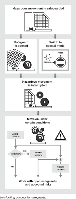
Experience shows that despite all the protestations, almost every safeguard has to be removed or opened at some point over the course of time. When safeguards are opened, it's fundamentally important that hazards are avoided where possible and that employees are protected from danger. The reason for opening, the frequency of opening and the actual risk involved in carrying out activities behind open safeguards (see the following illustrations) will determine the procedures used to attach and monitor safeguards.

Where safeguards are opened as a condition of operation or more frequently (for example: at least once per shift), this must be possible without using tools. Where there are hazardous situations, use of an interlock or guard locking device must be guaranteed. Further protective measures must be adjusted to suit the resulting risk and the drive/technological conditions, to ensure that the activities
which need to be carried out while the safeguards are open can be performed at an acceptable level of risk. This procedure conforms to the EC Machinery Directive. It allows work to be carried out while the safeguards are open as a special operating mode and gives this practice a legal basis.

Just some final words in conclusion for all designers: Designing interlocks so that absolutely no movement of the machine or subsections is possible once the safeguard has been opened actually encourages the type of conduct which is contrary to safety and, ultimately, leads to accidents. Nevertheless it is the causes you have to combat, not the people. If a machine does not operate as intended, users will feel they have no choice but to intervene. In all probability, the machine will “reciprocate” some time with an accident. Which is not actually what is was designed to do!