Sunday, November 27, 2011

What are the Changes to Europe’s Machinery Directive Every Manufacturer Must Know?


US manufacturers that export machinery to Europe need to be aware of the upcoming changes to the Machinery Directive.  When it comes to the design of safety related control systems the familiar standard EN 954-1 is set to be replaced by EN 62061 and EN ISO 13849-1. Pilz Automation Safety can help manufacturers understand this important change.
Where are the fundamental changes from EN 954-1? Previously the focus was on the architecture of the control system. Ultimately this was converted into “categories”. By contrast, the structure in the new standard EN ISO 13849-1 is simply stated on a qualitative basis. This means that quantitative variables such as the mean time to a dangerous failure (MTTFd), diagnostic coverage (DC) and common cause failures (CCF) have been added. Together, these parameters affect the performance level that can be achieved. Varying them also enables you to identify the optimum configuration. Due to these parameters, the new standard also considers aspects such as probability of failure and fault detection capabilities. These don’t just refer to the logic section. On a safety control system for example; the whole safety function is considered, from sensor to actuator. This overall assessment is nothing new in itself, but it does now have a different priority: as a result of the rigorous assessment in accordance with EN ISO 13849-1, it is now fully established and stipulated. The focus may now be on components such as valves for example, which were considered a lower priority under EN 954-1. In accordance with the new standard, these must now be included in the calculation with their characteristic data and reliability values.  
Machinery in the European Economic Area must comply with the Machinery Directive. The CE mark is the visible seal on the machine, which documents conformity with the Machinery Directive.   The change to the Machinery Directive takes place Dec 31, 2011. 
If a manufacturer does not want to use the standards to comply with the Machinery Directive, there is a more costly alternative, but for most manufacturers it is cost prohibitive and much slower to put into practice.

Monday, November 21, 2011

Rules for Exporting Machines to Europe Will Change Dec 31, 2011

 Companies that wish to export machinery to the European market need to make sure the machinery is safe and compliant with the Machinery Directive.  There are changes that will take place to this standard and they will take effect on December 31, 2011.  En 954-1 is the part of the Machinery Directive that will change.  EN 62061 and EN ISO 13849-1 are due to replace the familiar standard EN 954-1 when it comes to the design of safety related control systems.
The differences in the two standards can be summed up in the following:  EN ISO 13849-1 demands a probabilistic assessment of the safety functions, which goes beyond the “qualitative” approach of EN 954-1.  Pilz Automation Safety can help with making sure machinery is compliant with the new Machinery Directive.
There is no transition for this change.   In effect this means that if you continue to apply this standard, presumption of conformity as regards the Machinery Directive will no longer be triggered. To put it plainly: anyone who doesn’t get to grips with EN ISO 13849 will be running considerable risks as far as machine safety is concerned.
Machinery in the European Economic Area must comply with the Machinery Directive. The CE mark is the visible seal on the machine, which documents conformity with the Machinery Directive. Manufacturers use this to confirm compliance with the requirements of the Machinery Directive. In terms of actual implementation, the conformity process is supported by standards. In other words, when a standard is listed in the EU Official Journal, i.e. when the harmonized standard is available, you can benefit from presumption of conformity whenever it is applied. To put it another way: anyone who applies the relevant machine standards will have a safe machine, which may carry a CE mark provided all the other requirements have been considered.
There are more costly and slower alternatives to using standards to comply with the Machinery Directive, but they are generally cost prohibitive.

Thursday, November 17, 2011

Why Ethernet in automation technology?

Automation technology is currently developing away from a centralized control system with simple binary sensors and actuators into complex, intelligent systems. The proportion of control and process capacity within the sensors and actuators is constantly growing. This trend changes the communication requirements dramatically: Instead of the usual master/slave system that we see today, in future, more and more data will be exchanged
directly between the network subscribers. Today's individual, largely passive bus subscribers will increasingly assume the function of bus masters, with their own computing capacity.

Modern IT technology – as seen in office communication with personal computers and office network technology such as switches, routers etc. – currently offers a wide range of system components at favorable prices. There is huge potential for innovation. That's why users are increasingly keen to modify this technology to make it usable for industrial automation technology. Ethernet, which is practically standard in today's office communication, has a prominent role to play. When developing modern fieldbus systems, the aim in future must be to exploit the benefits of Ethernet to a greater extent. The installation of Ethernet systems must become simpler; compared with current fieldbus systems, Ethernet in its current form is still too complex.

The requirements of the individual elements of a production plant also continue to grow. This affects scan times, precision/frequency of measurements, data amounts and processor power, to name but a few. As far as the automation system is concerned, the performance of the process computer and communication systems must satisfy these growing requirements. As a modern, Ethernet-based fieldbus system, SafetyNET p meets these new requirements. At the same time, SafetyNET p is as simple to install and as reliable as today’s available fieldbus systems.

SafetyNET p system description
Safety-related communication via Ethernet is explained below, using the real-time Ethernet communication system SafetyNET p as an example. SafetyNET p is a multi-master bus system, i. e. all devices on the network have equal rights. The bus scan time of SafetyNET can be adapted to suit the application requirements.

Security
The protocol includes a safe data channel, which is certified for data transfer in accordance with SIL 3 of IEC 61508. Both safety-related and nonsafety-related data is transferred via the same bus cable. Non-safety-related subscribers have direct access to safety-related data and can use it for further non-safety-related processing tasks.

Flexible topology and scan time selection
SafetyNET p is extremely flexible, not just when it comes to selecting a suitable bus scan time, but also on the issue of the appropriate topology: The multi-master bus system supports linear, star, tree and ring topologies. The RTFL communication principle (Real Time Frame Line) is suitable for intra-cell communication, as it allows the fastest scan times. A minimum bus scan time of 62.5 μs can be achieved. Jobs and events can be recorded and executed with high precision across the entire network. Absolutely essential for real-time applications: a jitter of around 100 ns must be achievable in real-time control loops. As a result, it’s even
possible to use SafetyNET p in a frequency converter control loop between a rotary encoder and a speed regulator. Other highly dynamic applications are also possible, of course. RTFN mode (Real Time Frame Network) is used at higher levels, as it offers maximum coexistence capability with existing services.

Application layer
The interface with the application is made via widely-used CANopen technology. Existing CANopen devices can be converted to SafetyNET p devices simply by changing the transport layer.

Standard Ethernet technology
SafetyNET p uses Ethernet technology. The interface depends on the required performance level: If fastest possible communication is required, the RTFL communication principle is used, which is based on Ethernet OSI Layer 2 (MAC Frames). For communication via mixed Ethernet-based networks, from cell to cell or in general networks, UDP/IP communication is used. Conventional, standard Ethernet infrastructures can be used if the performance is satisfactory. This includes connectors, cables, routers, switches, gateways or communication channels.

Wednesday, November 16, 2011

Industries, applications for SafetyBUS p®

Industries, applications
Today, safe bus systems such as SafetyBUS p are used worldwide in a wide range of industries and applications. The list below represents only a selection.

Automotive industry
The automotive industry uses SafetyBUS p tosafeguard and control presses. Applications range from small standalone presses to multi-stage transfer presses, demanding the very highest safety and performance  requirements of a safety bus. Even on the conveyor technology, where the safety and reaction time requirements are not so high, safety-related fi eldbuses are used to collect widely distributed, safe I/O signals such as  E-STOPs. Robot cells are frequently found in the automotive industry and normally require safety gates, light curtains and E-STOP pushbuttons as safety equipment. With SafetyBUS p, multiple robot cells can be networked together and monitored via a safety control system.

SafetyBUS p in a robot application
Airports
Airports contain baggage handling and conveying technology applications in which long distances have to be covered. Safety-related equipment such as E-STOP push buttons and grab wires are distributed across the whole route. SafetyBUS p collects the safety-related signals and makes them available to the safety control system, which shuts down the drives safely if necessary.


Passenger transportation
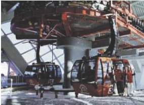
SafetyBUS p is also used for communication on cable cars: Safety-related signals are exchanged between the mountain and valley stations and signals are collected en route. Wireless or fiber-optic communication is used to cover the long distances.

Thursday, November 10, 2011

Safe wireless communication

SafetyBUS p data can be transmitted wirelessly using wireless routers. From the safety control system's perspective the wireless routers are transparent, i. e. they are not visible as subscribers in the network and therefore don't need to be configured. The wireless bus segment behaves in the same way as a segment connected via cable. Wireless transmission does not affect the safety level of SafetyBUS p.

Safe wireless communication
Safe wireless communication is used when it's necessary to span long distances between safety related subscribers but it is too complex and therefore cost inefficient to lay cables. Another application would be mobile subscribers, on which the wearing sliding contacts are replaced by wireless transmission for data transfer. These may be rotating or linear-moved plant sections, such as those found on automatic guided vehicle systems or cranes. When safe wireless technology is employed, high demands are placed above all on the quality of the wireless connection, as this affects the number of telegrams that are lost and can cause safety related shutdowns of the application. This in turn will impact on the application's availability. To guarantee the quality of the wireless connection, particular attention should be paid to selecting wireless and antenna technology that is appropriate for the application. Operating ranges of up to a kilometer can be implemented using an omnidirectional antenna, while up to 10 kilometers are possible with a directional antenna.

Wednesday, November 9, 2011

Certification of Safe fieldbus communication with SafetyBUS p®

Notified bodies such as TÜV and BG have approved safe communication via SafetyBUS p for use in safety-related applications in accordance with the following standards:

  • SIL 3 in accordance with IEC 61508
  • Category 4 in accordance with EN 954-1
  • PL e in accordance with ISO 13849
  • SIL 3 in accordance with IEC 62061

Diagnostics
Diagnostic information from the subscriber is made available to the Management Device, which is usually a safety control system. The safety control system can provide this information to common standard communication systems such as Profi bus DP, CANopen or Ethernet/IP, for example.

Communication media
A wide range of communication media is available to SafetyBUS p, enabling it to satisfy the varied application requirements. Communication may therefore be copper, wireless, light or fiber-optic based.

Fiber-optic communication
With fiber-optic (FO) communication, fiber-optic cables, transmitters and receivers are used instead of copper cables. Fibre-optic routers are used on SafetyBUS p for this purpose. For safety control systems with SafetyBUS p interface, the fiber-optic routers are totally transparent, i. e. copper-based communication can simply be swapped for fiber-optic communication, without having to reconfigure the control system. SafetyBUS p has a number of different devices for creating fiber-optic paths. Fiber-optic converters can be selected for glass fiber paths from 4 to 40 kilometres, depending on the application. Integrated routing functions enable network segmentation. As a result, different transmission rates are possible within the segments connected via FO. The FO router also filters messages in SafetyBUS p, so that they only reach the segments for which they are intended. This reduces the network load in the remote bus segment.

Today, FO communication is found in a wide range of applications. It's important where a high EMC load would disrupt communication, as would be the case with welding robots in the automotive industry, for example. Fiber-optic paths are also used for safety-related communication between the mountain and valley stations on cablecars, where it's necessary to span long distances outdoors. This technology is also used to reduce reaction times in safety technology. On copper-based networks, the data transmission rate depends on the cable runs, so the reaction time of the safety technology increases with the length of the bus cable. This dependency is lower on FO-based networks, so a short reaction time is guaranteed, even over long  distances.

Thursday, November 3, 2011

Separation of safety-related and standard communication

On SafetyBUS p, safety-related data is communicated separately from standard data, via separate bus cables. This division makes troubleshooting easier when faults occur. It also increases the system's availability, as there's no feedback between standard and safety-related communication. The reduced bus load also leads to faster reaction times. There is a clear allocation of responsibility for the data. As a result, unwanted or accidental modifications in the standard section will not infl uence the safety-related section. The restriction to a purely safety-related system means that complexity is low, which simplifies the engineering and approval process.

Notified bodies such as TÜV and BG have approved safe communication via SafetyBUS p for use in safety-related applications in accordance with the following standards:
  • SIL 3 in accordance with IEC 61508
  • Category 4 in accordance with EN 954-1
  • PL e in accordance with ISO 13849
  • SIL 3 in accordance with IEC 62061
Diagnostic information from the subscriber is made available to the Management Device, which is usually a safety control system. The safety control system can provide this information to common standard communication systems such as Profibus DP, CANopen or Ethernet/IP, for example.

A wide range of communication media is available to SafetyBUS p, enabling it to satisfy the varied application requirements. Communication may therefore be copper, wireless, light or fiber-optic based.

Tuesday, November 1, 2011

Security measures of SafetyBUS p

The following security measures are implemented on SafetyBUS p in order to detect communication errors:
  • Counters
  • Addresses
  • Acknowledgements
  • Time monitoring (timeout)
  • Connection monitoring
  • Cyclical polling with timeout
  • Safe hardware
  • Redundant and diverse chips 
Up to 64 safe devices can be implemented within a network using the multimaster system SafetyBUS p. This can even be extended to up to 128 subscribers if networks are interconnected, enabling 4,000 inputs and outputs per network.

Further technical features:
  • Guaranteed error reaction times up to 25 ms
  • Safe usable data per telegram: 32 Bit
  • Maximum cable runs:
  • Copper cables: 3.5 km, fi bre-optic: 40 km
  • Multiple networks can be safely interconnected
  • Gateways to standard fi eldbuses
  • Optional supply voltage via bus cable